
Quadcopter
During the summer of 2020 I undertook a project to build my own remote controlled quadcopter. While researching the workings of quadcopters, I learned about IMUs and the process of how a quadcopter levels itself. Deciding upon an IMU consisting of a 3-axis gyroscope and 3-axis accelerometer, I purchased the necessary hardware to begin building. I chose brushless DC motors for this project because of their high torque to weight ratio, high efficiency, and greater reliability compared to their brushed counter parts.
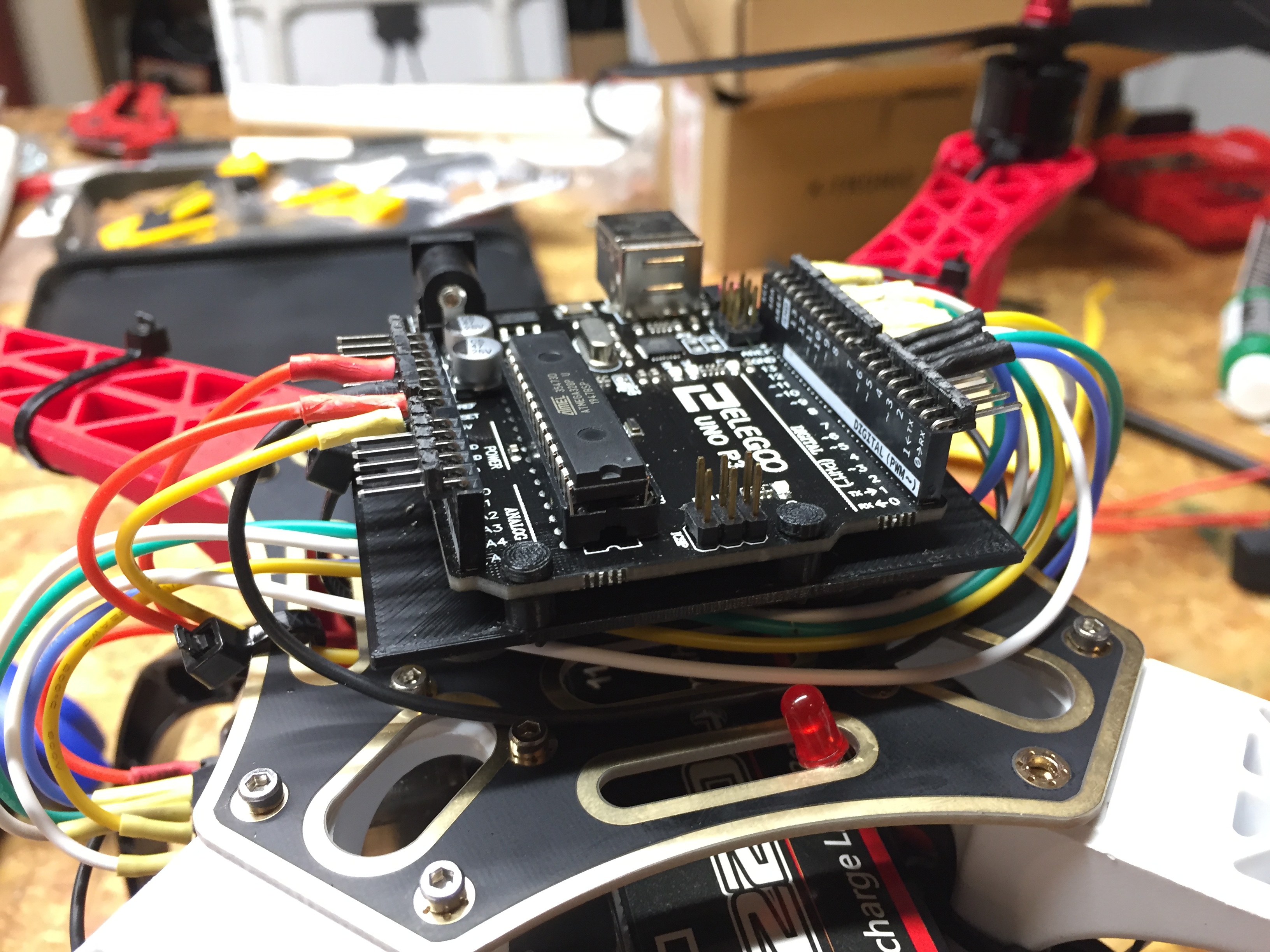
Mounted Arduino UNO
For the flight controller, I used an Arduino UNO due to its ease of programming and its large current output compared to the Arduino mini. I mounted the Arduino above the surface of the frame in order to place the IMU at the center of the quadcopter. That way the vibrations from the motors would have the smallest effect on the IMU. The mount for the Arduino and for the IMU were both designed in Solidworks and then 3D printed. A 3s, 2200mAh lipo battery was used to power the quadcopter, directly powering the ESCs, DC motors, and the Arduino. The 5V pin on the Arduino was used to power both the IMU and the receiver, separating them from the ~12V circuit powering the motors. Additionally, an indicator LED was mounted on the front of the quadcopter to indicate status while calibrating the gyro and to indicate low battery during flight.
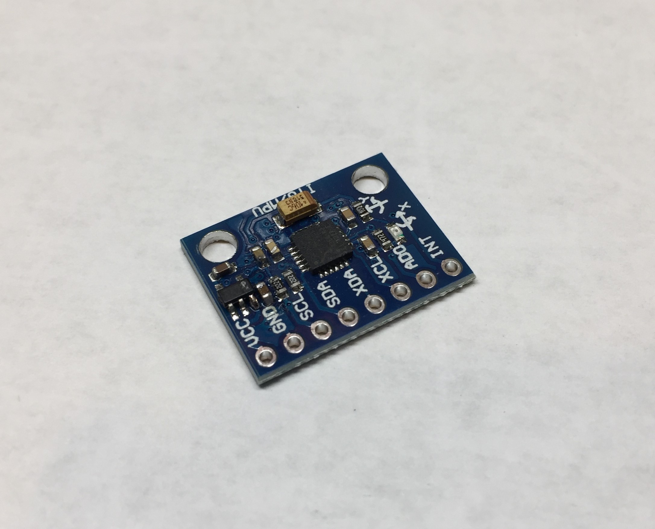
MPU-6050 Gyroscope/Accelerometer
I chose the MPU-6050 gyro/accelerometer because it contained everything I needed for the IMU on one board and was 5V compatible. The IMU mainly used the motion detected by the gyro to determine the quadcopter position. The accelerometer was used to determine the quadcopter’s initial position upon powering on, and to add a small correction for the drift of the gyro during flight. The Arduino’s flight controller software used PID control for all 3 axes of motion.
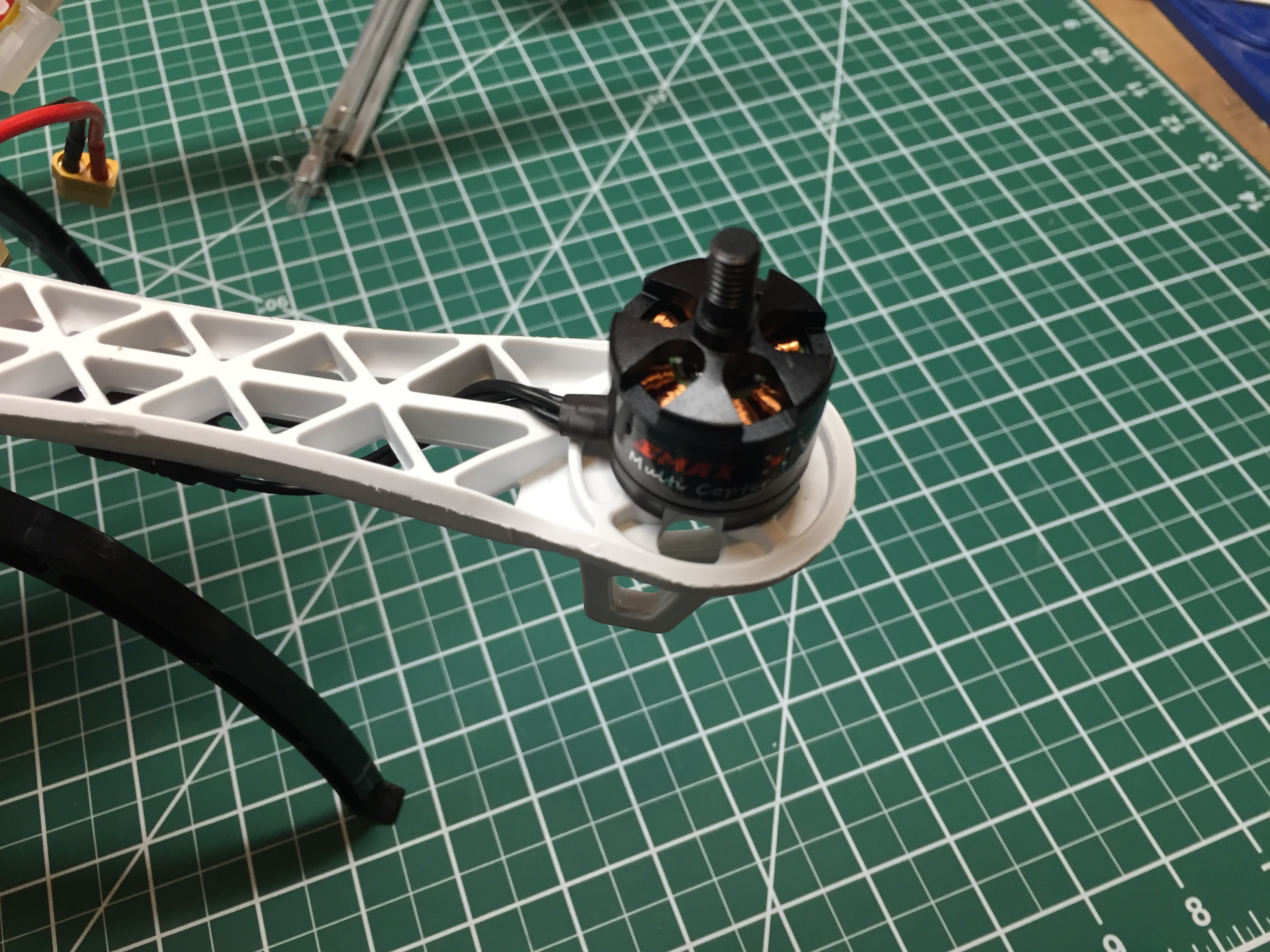
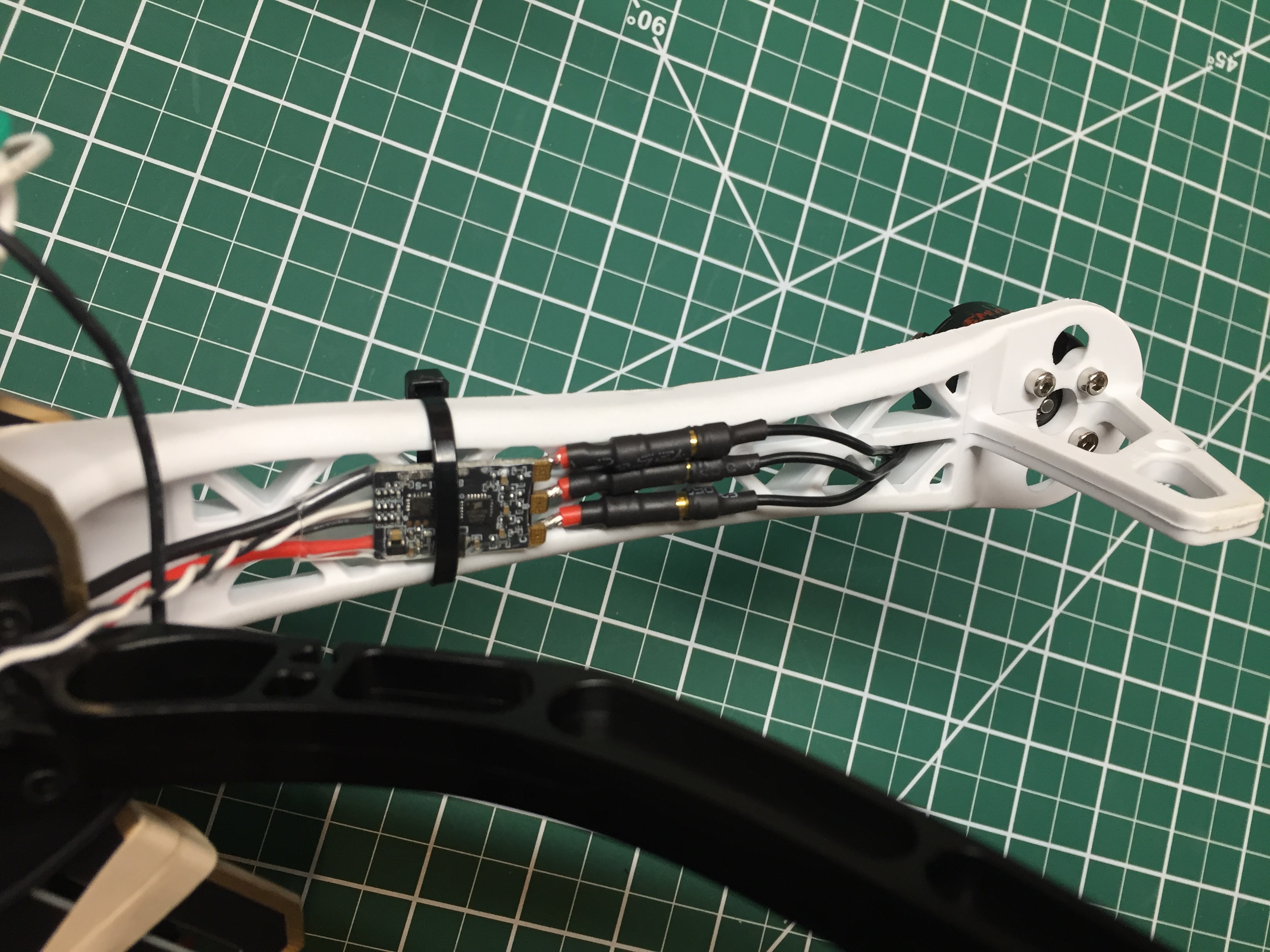
Brushless DC Motor and ESC
Each of the motors was controlled by sending a 1000 - 2000$\mu$s pulse to the ESCs. A 1000$\mu$s pulse corresponding to no motion, and a 2000$\mu$s pulse corresponding to full speed. The transmitter also used 1000 - 2000$\mu$s pulses to communicate with the receiver. The angles calculated from the gyro/accelerometer readings were compared to the pulses from the transmitter to determine the error for the PID controller. To determine the appropriate gains for each of the terms in the controller, I started by setting all of the gains to 0. Starting with proportional, I increased the gain in small increments until the quadcopter was able to fly. Next I increased the derivative and then integral gains until the quadcopter was stable.
All in all, I was able to build a quadcopter that self-leveled and flew reliably with a flight time of ~8 minutes per battery charge. I learned a lot about brushless DC motors, 3D printing, and PID control from this project. Due to the time sensitivity of the program loop, I also learned a lot about register programming and its advantages.